
Top 10 Features: Analysis tools and Quality Check – Part 3
With this issue we complete the series of articles on the powerful tools provided by ThinkDesign GSM. We will describe the tools that allow the analysis of the appearance and shape characteristics of a 3D model, through methods of measurement and comparison.
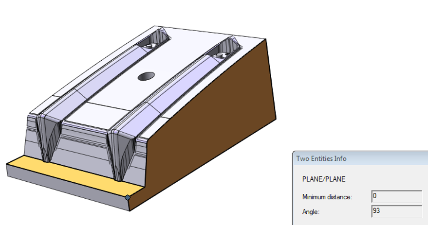
A basic tool is represented by ‘Two Entities’: through the simple selection of two entities, in fact it is possible to get a series of useful information for the design, from the distance between 2 points, up to the possibility of verifying (by selecting two curves, or a curve and a surface), the minimum distance and the possible co-planarity between these entities. In the case of selection of two planes it is possible to measure the draft angle or, in the case of parallel planes, the distance between them, useful, for example for the purposes of a correct assembly.
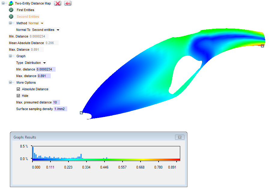
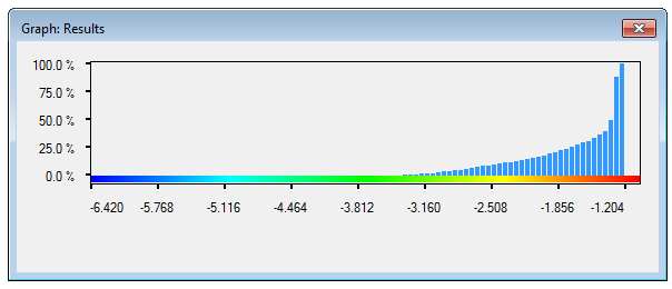
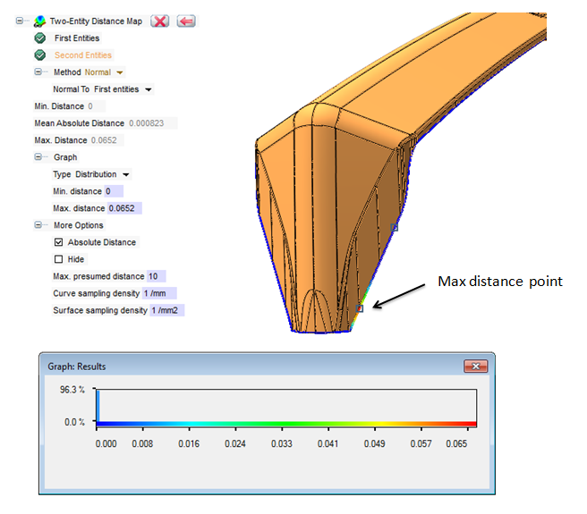
A further possibility of control is offered by the command ‘Two Entities Distance Map’. With this feature it is possible to analyze two entities, typically two surfaces, and represent the different relating distances and the areas of maximum and minimum distance, through a diagram and a different coloring. The possibility to analyze also the distances between curves and mesh files, greatly extends the range of use of this feature.
For example, in plastic molded objects, the thickness of the material in the various points of the shape is of particular importance in the design phase. In the presence of complex shapes, for needs of strength or for appearance reasons related to the shrinkage of the plastic material during the molding, it is necessary to produce models with variable offsets and this requires even complex modeling. With this tool, by selecting, for example, the external surfaces rather than the internal ones, it is possible to immediately get the distance between the points and check that thickness in the various areas of the designed model matches the requirements.
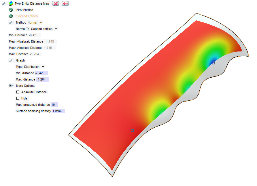
This command can be particularly helpful also in another typical case of mold design: the identification of eventual distance points between the mold parting line and the detail surfaces. In this case the ‘Two Entities Distance Map‘ command allows the selection of both the surfaces/skins of the detail and the mold division curves that will be used. In the case of imported geometries, where tolerances of conversion are involved, or when using approximated separating curves, it is possible to identify immediately non-contact areas and quantify and calculate their distances with respect to the normal, or with respect to a given direction (for example the direction of expansion of the separating plane).
In some typical situations, the CAD systems can be used to process also geometries of mesh type. The mesh could be result from a scan of the detail prototype that has shrunk, probably because of the development process, or from a scan of the same prototype that has been changed manually.
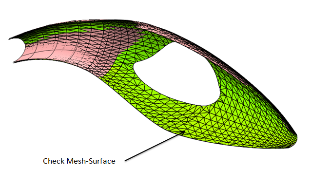
By outlining the prototype from the 3D scan or from a tracing process, and then importing the mesh file into the model, it is possible to analyze the surfaces of the initial model and the imported mesh, obtaining the display of the modified areas.
In the case of collaboration with third parties during the design phase, it is extremely important to have the possibility to quickly check eventual changes that might have been made to the model. Suppose to have started the designing of a mold and that is changed by other operators. Upon receipt of the “new” geometry it is essential to immediately identify the parts of the model that have been changed.
This is possible through the command ‘Check Design Differences‘, which allows the comparison between two geometries (solids or surfaces) and the identification of the faces of the shape that have been changed, added or deleted.
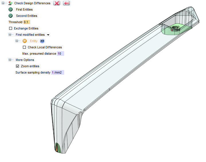
The ‘Exchange Entities‘ option allows a quick preview of the modified entities, alternating the original faces with the changed ones. Moreover it is possible to quantify the changes on the highlighted face through a local analysis.

The use of this set of tools allows the user to keep the quality of the project under control, as well as to anticipate and reduce the design assessments, reduce the design errors, with obvious significant quality improvements and time saving.