Top 10 Features: Carpentry Frames
Here is a new article of the series written by our experts on the main features of ThinkDesign. Today’s topic is Carpentry frames.
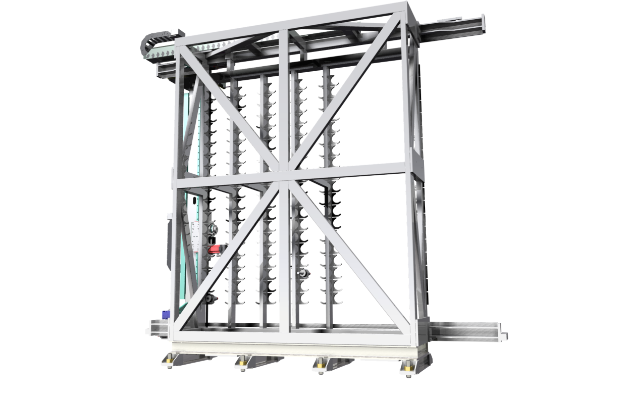
The word “Frame” generally stands for an assembly of metallic carpentry consisting of tubes, beams, reinforcement plates, cut tubes, tubing butted and assembled together by means of welds or fasteners. Frames are used, for examples, to support machinery or equipment, to create structural frames, casings, galleries, etc.
The main characteristic of these assemblies, in terms of design, is the simplicity in the geometry of the details, generally linear extrusions with cut and hole features. At the same time, however, these assemblies are complex, given the large number of details that they contain and must be managed. Consider, for example, the management of the encoding of the details, the production of the final drawings, the creation of the bill of materials, the calculation of the cut weights and lengths.
The creation of a carpentry frame, directly inside the 3D environment, entails considerable advantages for the designer under different points of view, both in terms of speed in the execution of the design, and in the ability to assess overall dimensions and interferences. Additional benefits are the automatic calculation of all the materials used and the automatic creation of the necessary cutting list.
Moreover, the 3D design allows you to achieve a high level of precision in the details and in the cuts of the nodes, thus enhancing the quality of the product and assuring a more efficient production thanks to the integration of the 3D geometry with the various machining technologies (consider, for instance, the new technologies of the 3D laser cutting).
To create frame structures, ThinkDesign provides, besides the solid modeling and base assembly features, 3 more valuable tools:
- The Frame function
- A library of standard parts and section bars
- 2D and 3D environment for the parametric sketch.
A typical approach
In the definition of a structure, the starting point is a parametric profile consisting of lines that represent the main dimensions of the support structure to be created. You can start from an analysis of a 2D sketch, then move to the 3D sketch, and define the “skeleton” of the frame. The lines constitute the main axes on which, subsequently the Frame function will extrude the sections. The 3D sketch environment is a parametric environment that allows a simplified approach to build, move/copy, adjust curves and polylines and ultimately define the profile. It is also possible to use the option “Work Plan on Last Point” to redefine the work plane when creating the lines and the 3D point snap with respect to a fixed direction.
A library of section bars provides the main sections of the standard extrusions, namely square rectangular or circular sections, plates, channels, angles, and various types of beams (HEA, IPE .. .), to be used with the “Frame Parts” command.
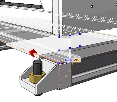
With this command, it is possible to select the lines directly on the parametric profile. In this way, all the rods of the frame will be parametric and, by simply changing the dimensions of the profiles used, it will be possible to automatically update the entire structure. Additional options allow the selection of the origin and the orientation of the section used, while the previews will allow you to select simply and interactively the correct parameters to achieve the desired feature.
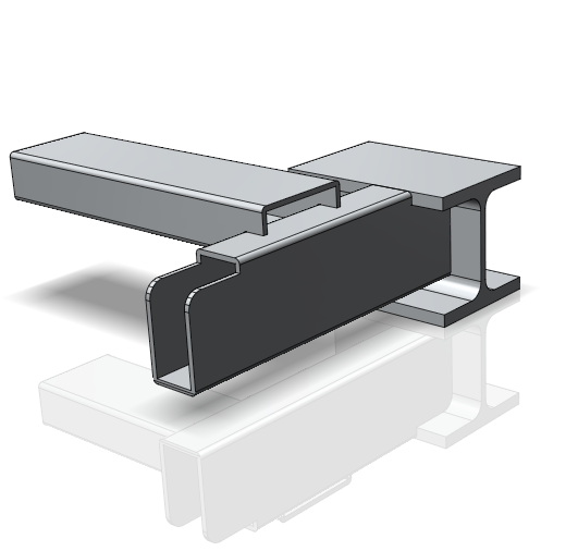
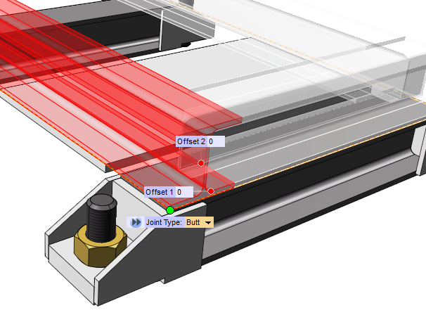
During the construction, if you select more lines of the same profile, having a common vertex, the nodes will be automatically recognized and managed. If more rods end at the same vertex (i.e. in a node) the system suggests various solutions to end and cut the rod (disjoined, miter, butt).
The user can confirm the creation of the solids and, with a specific option, the automatic creation of components. In this case the component of each rod is automatically created, with the advantage of directly obtaining a frame assembly, without managing complex relationships deriving from the positioning of the parts. Each component can be still further modified by applying standard features such as holes for fasteners or lightening.
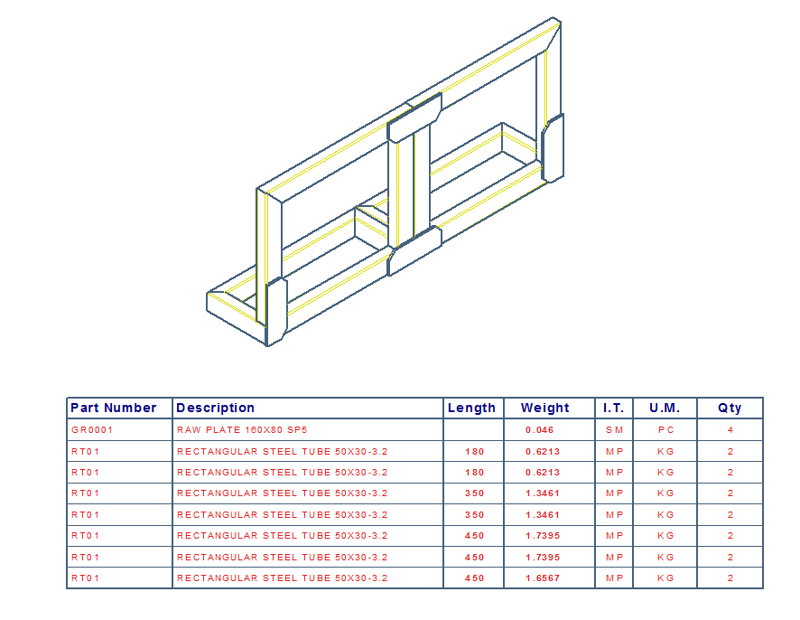
If the used profiles is already encoded, the code and the relating information will be automatic assigned to the single parts.
This method is particularly effective if a specific encoding is not requested for the semi-finished components. In fact in this way, the frame rods that use the same section bar, as raw material, will have the same code and the related bill of materials will be further simplified. The cutting length and the weight of the detail are handled by ThinkDesign, and automatically assigned as properties to the frame component. They contribute to the definition of the bill of materials and of the cutting list.