Top 10 Features: Integrated 2D/3D environment
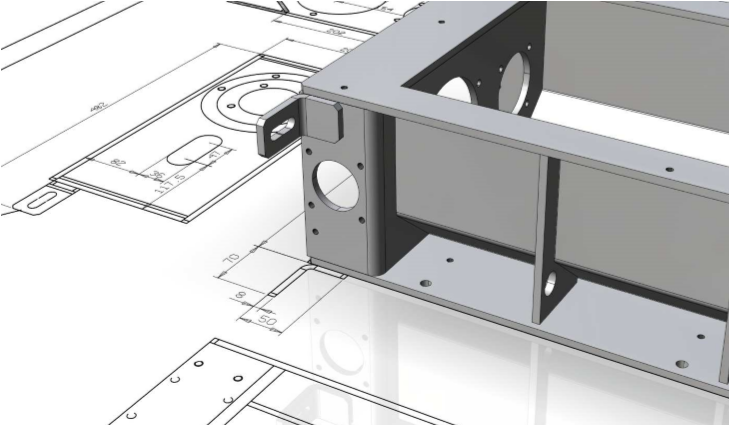
ThinkDesign provides a unique design environment with 2D and 3D features as well. This still represents a great advantage to the users. Let’s see why it must not be underestimated.
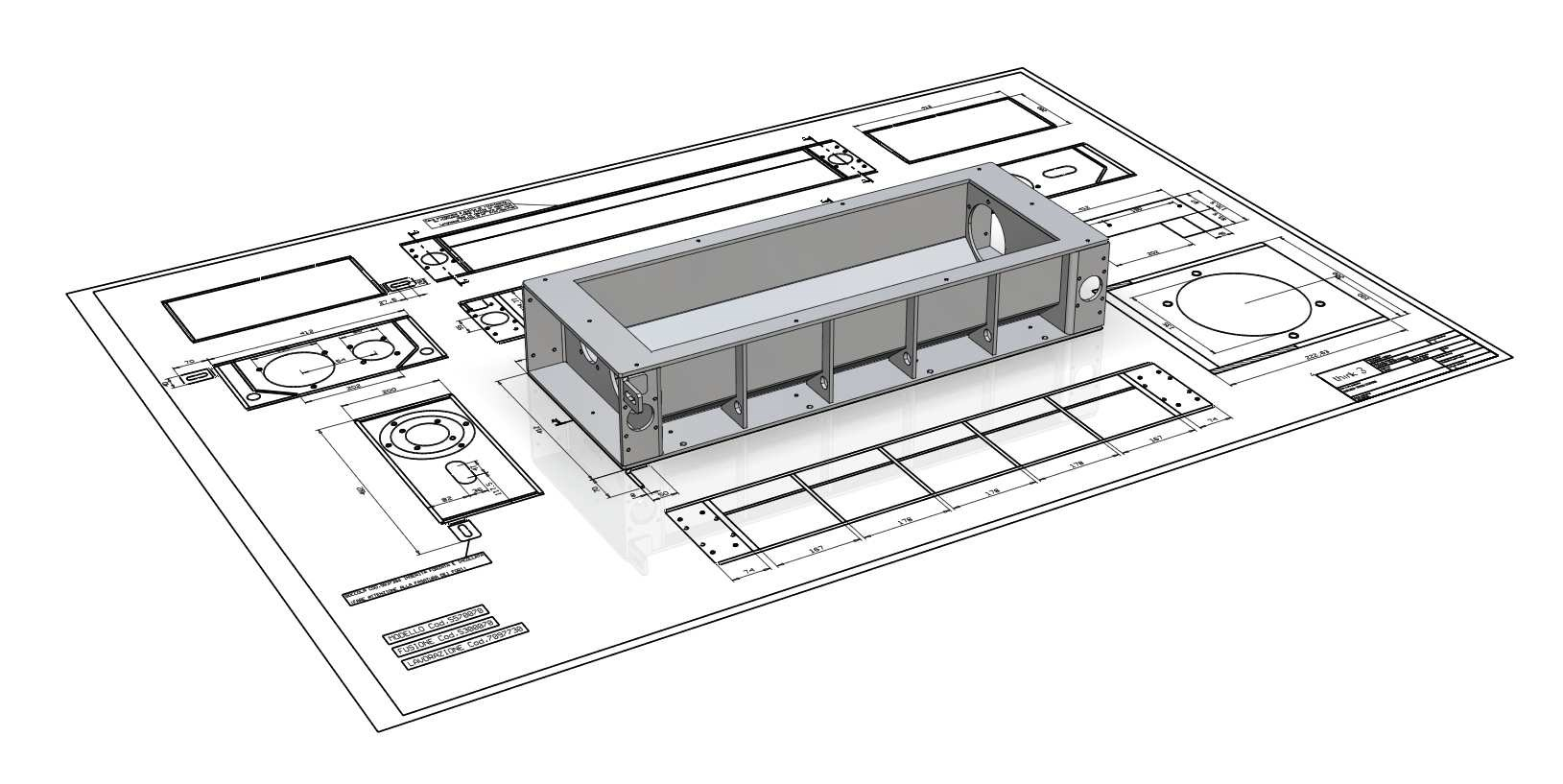

The evolution of design systems involved the development of technical documentation to support the processes of organization and production in the manufacturing companies. This trend came from a modern approach addressed directly to 3D design. However, nowadays, in many companies, the use of 2D drawing is still widespread.
Also the final documentation consists in great part of 2D drawings relating to the production and assembly phases, besides the 3D models. Some users consider the 2D approach more effective in terms of time-to-market, for some design projects. In fact, the 2D drawing is considered a universal way to represent and communicate an idea. Moreover, the spread use of standard rules has encouraged the development of a formal mode to synthesize the project data that need to be shared.
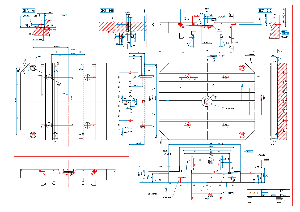
Working in an integrated design environment allows the full exploitation of 2D and 3D benefits, covering a wide range of still relevant needs for the users of ThinkDesign. Here are some examples:
- Choosing the desired approach, which often depends on the designer’s ability, or on the types of data to be managed;
- Importing and recovering 2D drawing archives and modifying them with instruments of mere drafting;
- Possibility of studying sections and layouts of a mechanical assembly, during the concept design phase, and freely draw dimensions, lines and simple geometric references.
Some examples of use:
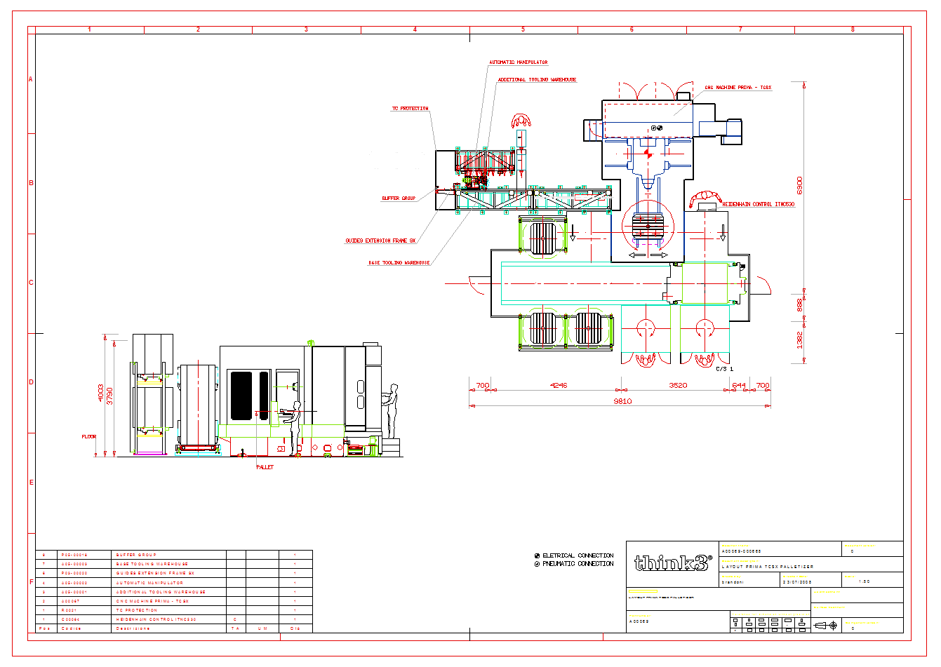
- The use of mere drafting features, available in the drawing environment, allows you to adopt a traditional 2D design approach; the availability of drafting commands, an effective standard-compliant dimensioning system, libraries and group libraries, and the opportunity to organize the drawing by groups, helps to make ThinkDesign the ideal environment for the design of layouts, industrial plants and technical data sheets.
- In the model environment, 2D entities coexist with parametric profiles, solids and assembly structures. Through a simple Copy & Paste, the drawing views can be imported to the 3D model, by selecting the appropriate reference plane. These views can then be reused to create new parametric profiles or directly as curves in the creation of solids and surfaces, or even as a reference for measurements or point snaps.
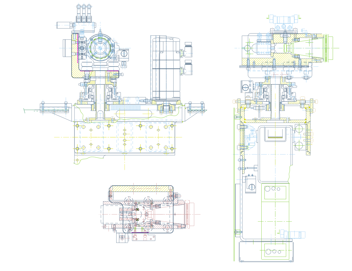
Drawing of a Tool Change Group in 2D format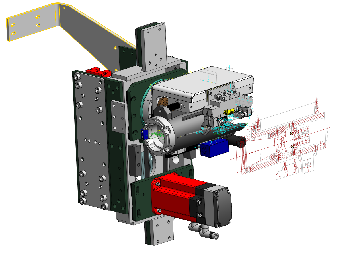 Assembly model, imported section and reference curves of a Tool Change Group
 - Thanks to the 2D/3D integration, the drafting and dimensioning commands can be used both in the drawing and in the model environment, thus making the work certainly easier and simplifying a 3D design approach. The ‘Multi-Stretch’ command used in the profile environment, for example, allows the user to easily modify the underconstrained profile geometry with the same approach used for modifying a 2D drawing.
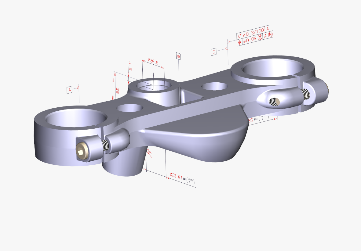
- The dimensioning and drafting commands can be used directly in the 3D model in order to add, to the design, annotations, measured dimensions and tolerance symbols, providing useful information for the production (PMI – Product Manufacturing Information) of the detail.
