
Top 10 Features: Interactive Modeling – Part 2
Let’s continue with our “Top Ten” and face Part II of Interactive Modeling.
In the previous article, we illustrated how Interactive Modeling leaves the designer more freedom of intervention, even at an advanced stage of design of a parametric History-based solid model.
In this way, the designer is free to make changes with certain flexibility, without having to deal with the relations and constraints imposed by a parametric History-based modeling.
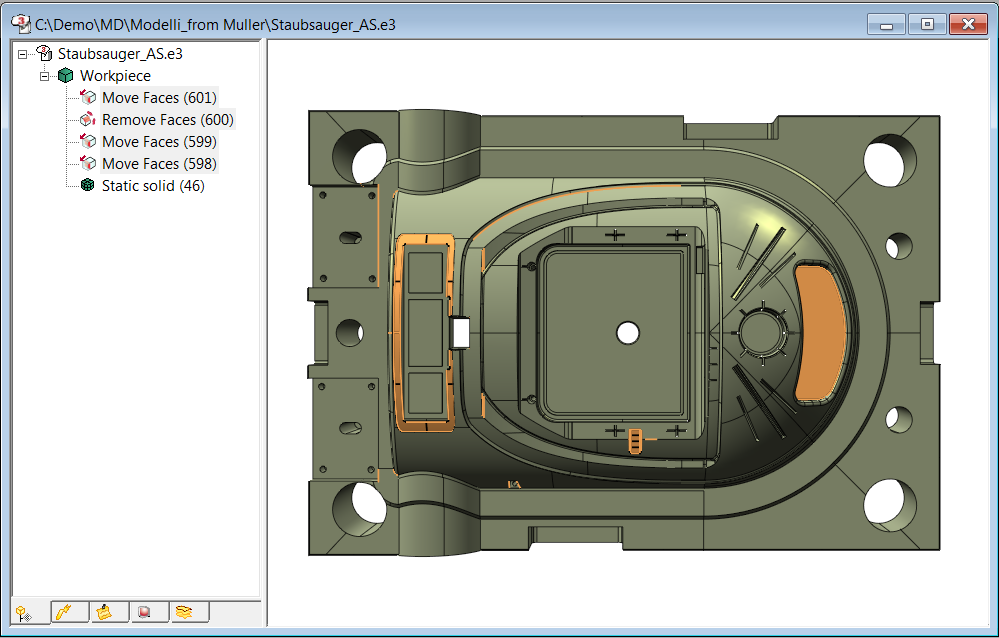
One of the most interesting aspects of Interactive Modeling is the fact that it can be applied also to imported geometries, i.e. static and not History-based.
There is a variety of possibilities of changes that involve a number of advantages, such as the ability to perform operations on solid objects rather than on individual surfaces, a considerable saving in terms of time and work, a reduction of the Trim/Untrim features and a quicker execution of the desired changes.
Interactive Modeling also creates events that become part of the history of the imported model, thus allowing an easy redefinition of the features carried out directly through the Model Tree.
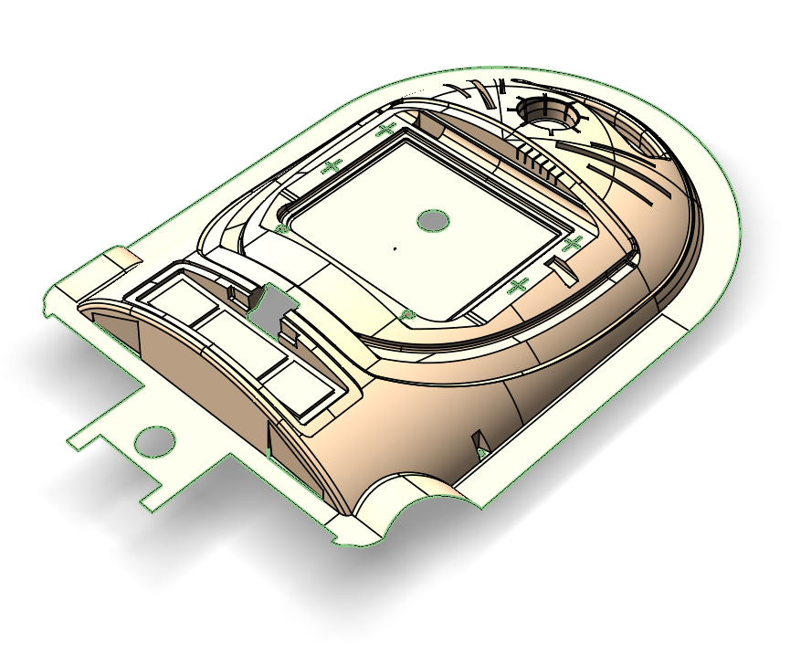
In the presence of imported geometries, it is often necessary to operate on open solids (skins). In case of problems in closing the solid or of gaps in the intersections between the boundaries of the faces, Interactive Modeling, represents a powerful tool, thanks to the command ‘Extend Faces/ Close Solid’, to get a closed solid and improve the quality of the final result.
A first valuable support is provided by the possibility of identifying the open zones. By applying the command in ‘Local’ mode, the user is prompted to select a skin with open zones or boundaries between not properly trimmed faces. In this way, the boundaries of the open zones will be highlighted in green.
By selecting the affected zones, the command “Close Solid” will look for the intersection boundaries between the faces, correcting where possible topology errors. It is possible to proceed either adopting a method of extension by parameter – useful in case of plans and rational surfaces like cylinders – or, as an alternative, following an approach of extension by tangency, more suitable in case of NURBS and approximate surfaces.
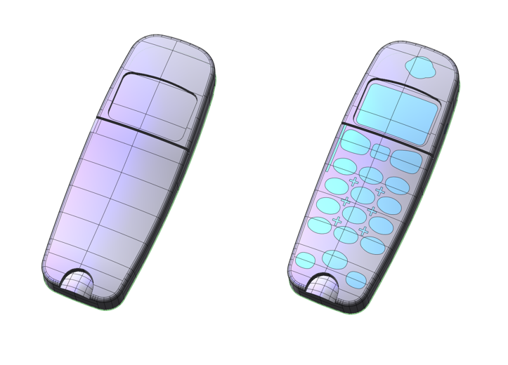
During the creation of separation surfaces in a mold, a very challenging task is the generation of the surfaces necessary to close the inner holes.
In this case, the ‘Close Solid’ command, in ‘Local’ mode allows also the use of the command ‘Insert New Faces’ that creates the new faces of the solid by closing the gaps. Moreover, with the option ‘Keep Face Color’, the color is assigned to the newly created faces, thus making it is easier to distinguish them from the existing ones and facilitating their selection through the filter by color in case of reuse.
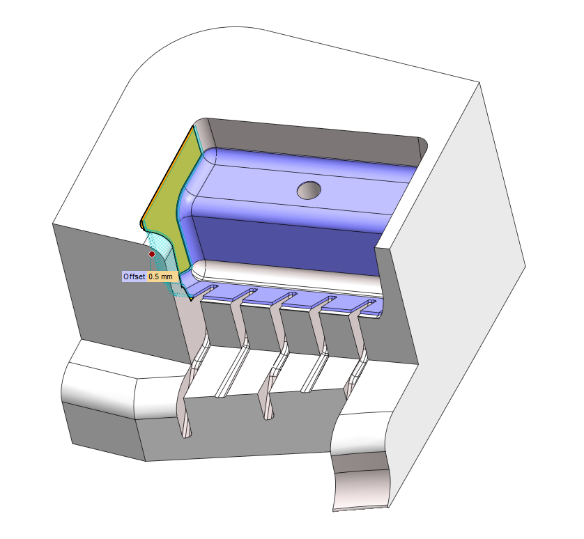
In the final stage, some changes might be required to the model thickness, for example, after the molding analysis or after the results obtained with the FEM simulation on load strength of the designed detail.
Also in this case, thanks to the Offset command, it is possible to intervene on topology, by selecting the faces to which the selected thickness must be applied.
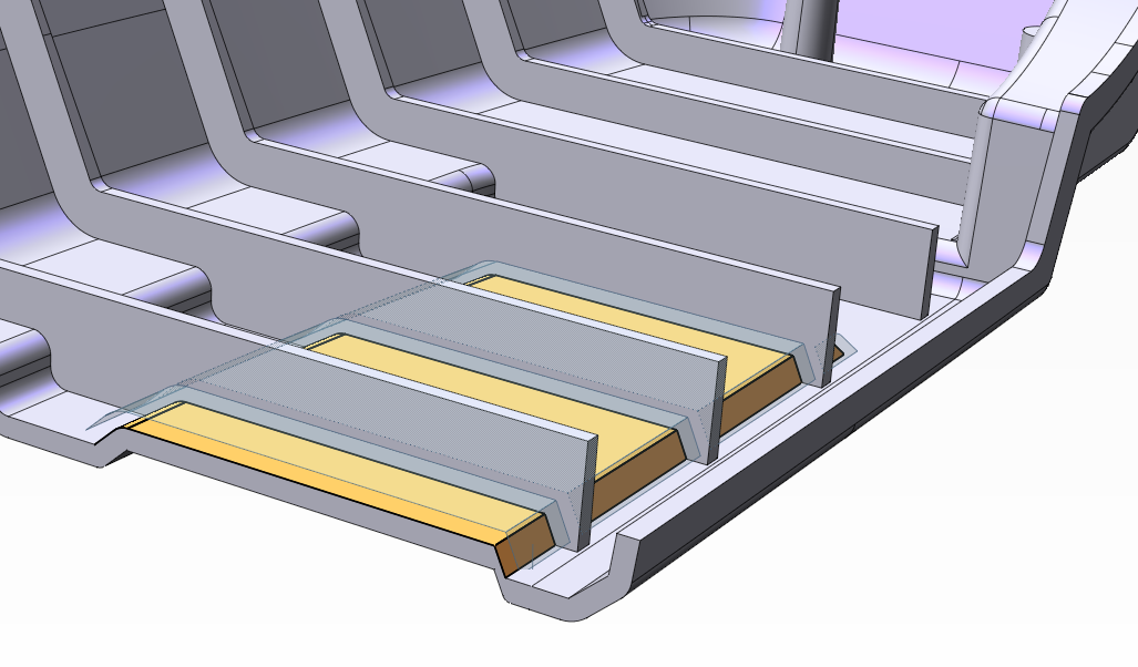
Where, for reasons related to the particular geometry or tangency conditions, the offset finds no intersections with the adjacent faces, by enabling the ‘Side Faces’ option, it is possible to generate the side faces perpendicular to the direction of the offset for each boundary of the face.
You just have to try, see you with the next article!