THINKDESIGN FEATURES
Learn and explore what ThinkDesign allows you to do.
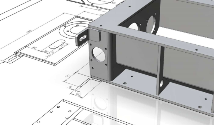
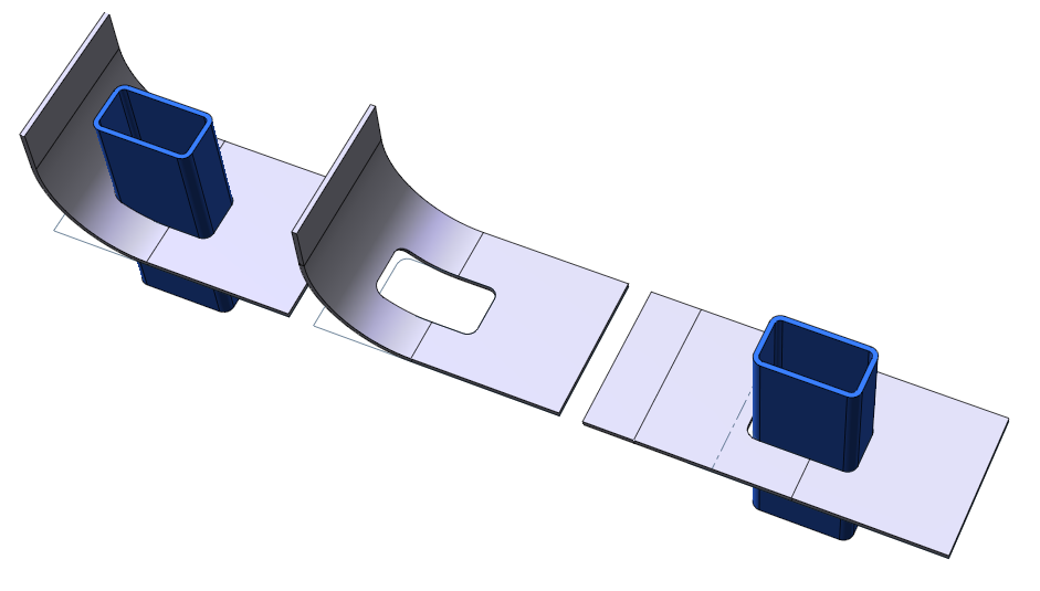
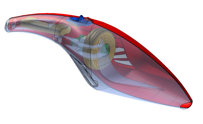
Hybrid modeling
Solids and surfaces interoperability
ThinkDesign is a true Hybrid Modeler: it allows one to work simultaneously on wireframe, surface models or solid models - all in one environment. Solids and surfaces can be used in basic construction operations, and associativity is keep between all entities.ThinkDesign can also handle 'open' solids (non-manifold solids, or solids with no volume), which is often the case when dealing with imported geometry.
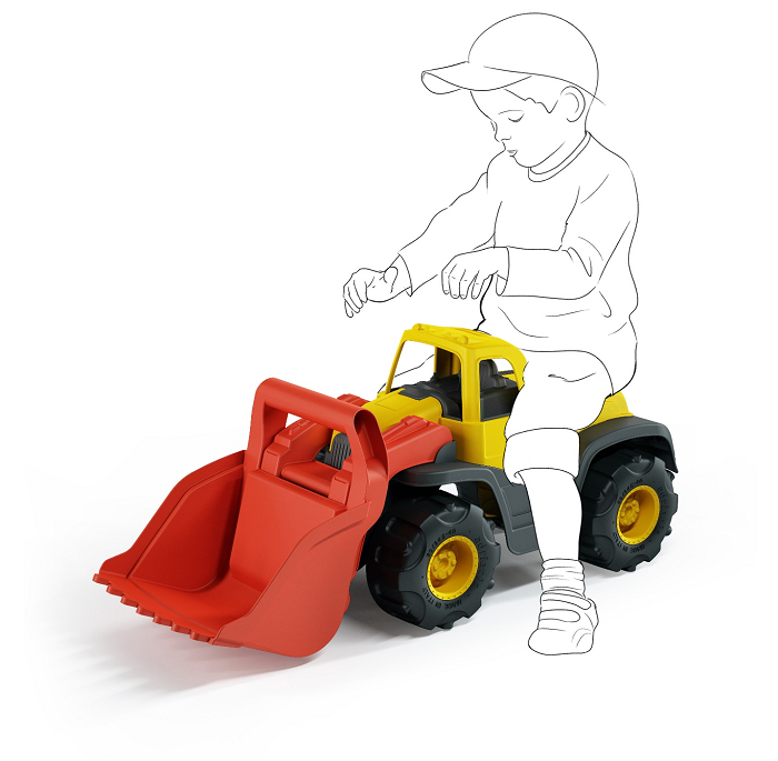
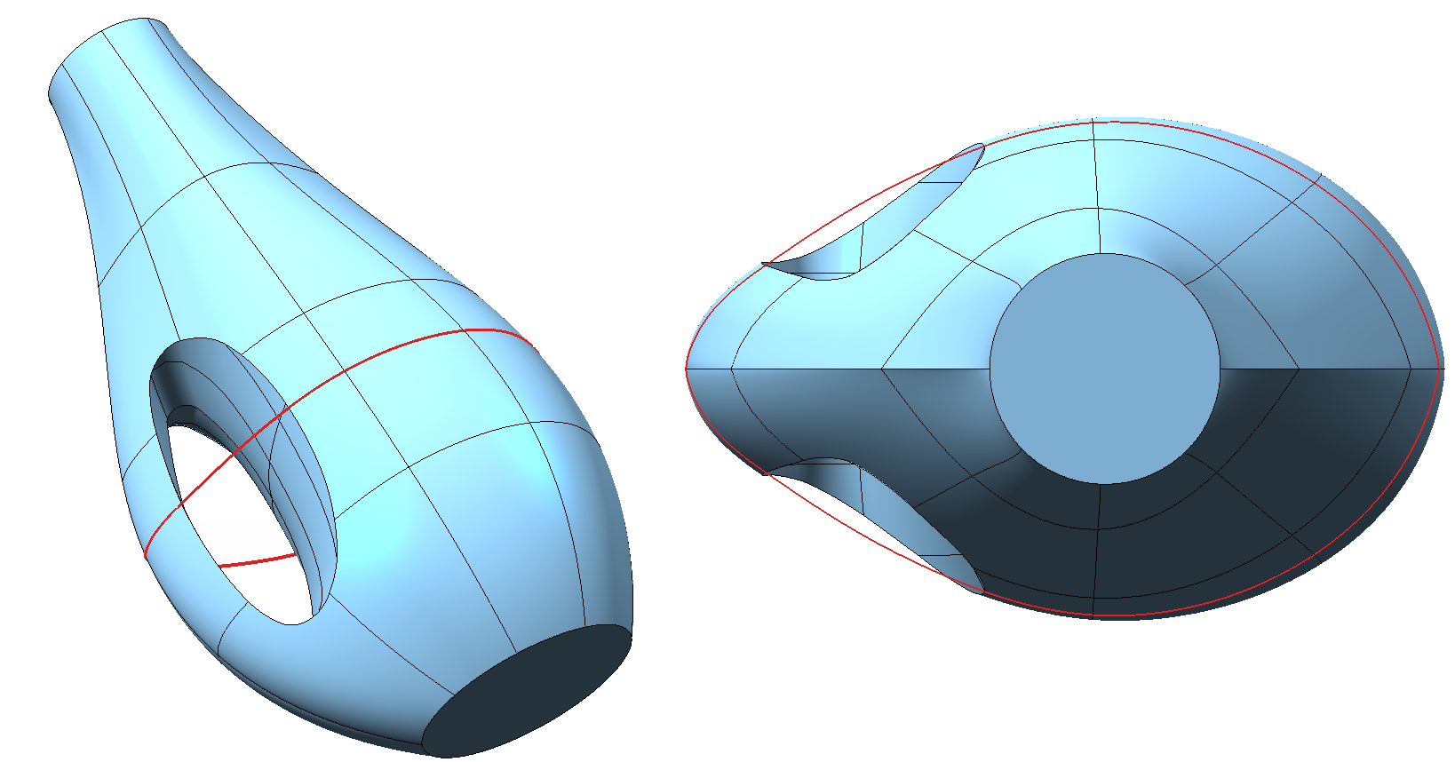
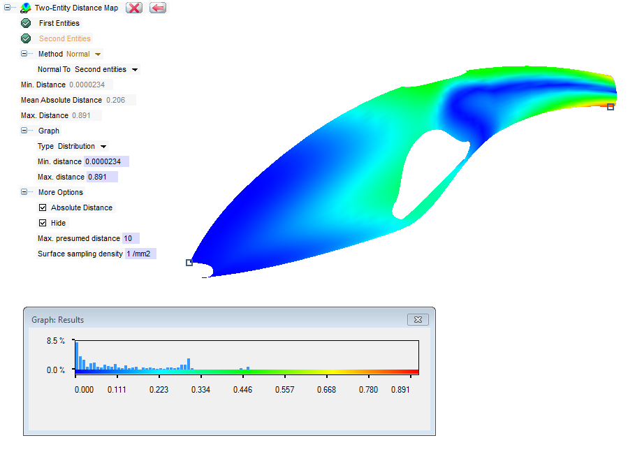
Global Shape Modeling
think3’s Global Shape Modeling, now called GSM, provides designers a very high level of technological innovation with unrivalled ease of use. It is currently the only creation and modification tool that allows changes in a quick and accurate way in any stage of the design process, accelerating interactions with unlimited creativity and eliminating the need to rebuild models. GSM has become famous and much appreciated because it makes complex changes happen in minutes instead of hours or days.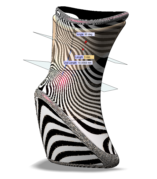
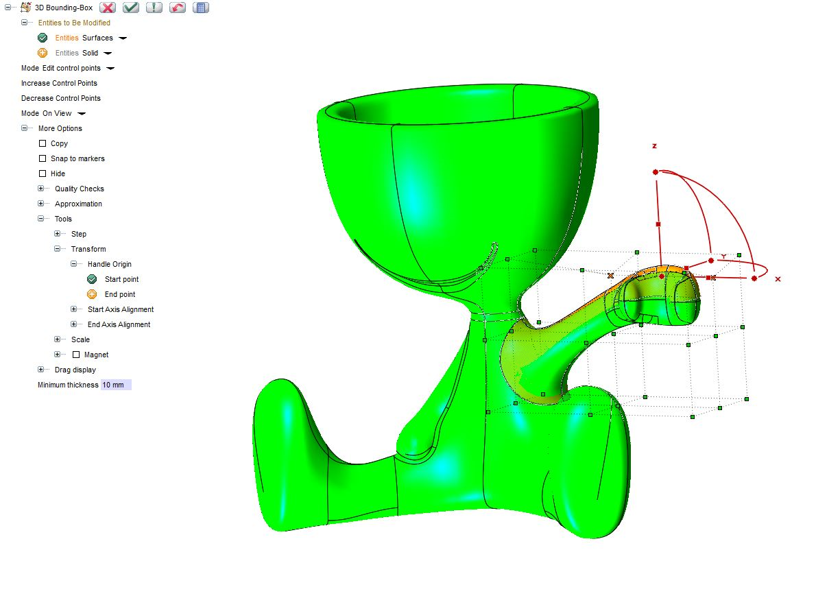

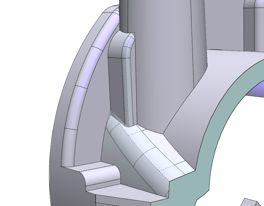
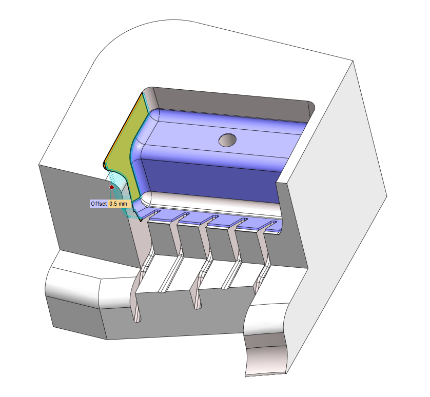
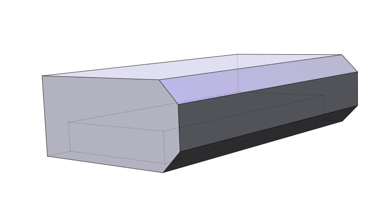
Zone Modeling and Zone Draft
The Zone Modeling command enables you to apply all of the GSM functionalities to selected zones (faces) of a solid model. It can be used efficiently to locally modify a solid by applying a controlled modification to a certain area. Together with the 'Insert Feature Mode' command, it can be used to modify a zone of a solid and propagate the controlled modification to subsequent features.Zone Draft enables users to add a draft angle to one or more zones (faces) of a solid. The corresponding drive dimension is also added. This command is particularly useful in those situations where technicians need to add a draft angle to complex models after the model's creation. When this change must be at the very end of the design process - and especially to static solids imported from other environments - Zone Draft is a fast and reliable tool. It is very useful in the process of mold and tool creation.