
Top 10 Features: Interactive Modeling
In the “Top Ten” ranking, Interactive Modeling is certainly among the most popular features of ThinkDesign.
This new approach, combined with a set of other specific functions of our CAD, offers a “complementary” method to the History-based parametric modeling for changing solids.
In this article we will analyze the main features of this approach, describe its advantages and show when it is convenient to use it.
In a general-purpose CAD such as ThinkDesign, which provides powerful modeling tools and different approaches to Parametric and Hybrid Associative Modeling, one wonders why it was important to introduce an additional mode.
The need arose from two main specific reasons:
- In a complex parametric model, with many features and many constraints, is it possible to predict the result of a change?
- How can an imported static solid be changed in a simple and efficient way?
Through Interactive Modeling it is possible to apply topological changes to the Solid such as Move, Remove, Replace Faces, or Offset Faces, or Extend Faces/Close Solid without having at one’s disposal the model history and parameters. Interactive Modeling can be applied by directly selecting the faces of the solid to be changed and, therefore, without redefining the parameters of the history of the parametric modeling.
Interactive Modeling
In the Parametric Modeling, features follow a History-based approach: changes depend on the possibility to redefine and regenerate the processing sequence. In a mechanical part, for example in a plate, the holes can be positioned by making reference to the distance of the edge generated by a slot feature previously created. In a History-based approach, it is therefore advantageous to be able to insert these constraints. In our example, when the designer modifies the slot, s/he can rely on the distance of the holes because s/he has defined that design constraint. By following this approach, it is always possible to control the processing, but it is also necessary to keep in mind the defined constraints. If, after some time, another designer carries out the change or if the features become more complex, tracking and controlling the inserted constraints can be hard. In other cases the constraints themselves are so complex that performing the change can be difficult, and, a tight deadline for the deliverable can increase the designer’s stress.
Interactive Modeling removes these barriers, offering the designer, who must perform the “last minute change”, a flexible and quick alternative.
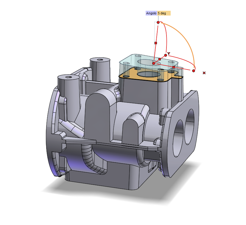
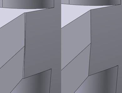
Consider, for example, the need to move a housing seat, whose faces are generated with more features, like slots, fillets and holes. With Interactive Modeling, by selecting the involved faces and using the Move Faces command, the change can be carried out quickly without the need to take into account the sequence of operations that produced that geometry. As last operation, run again the “Move Faces” command: the previous modeling history and its constraints, if any, are not changed and any features linked to these constraints remain unchanged. With this approach the designer is free to change the geometry ignoring the constraints.
Move Faces
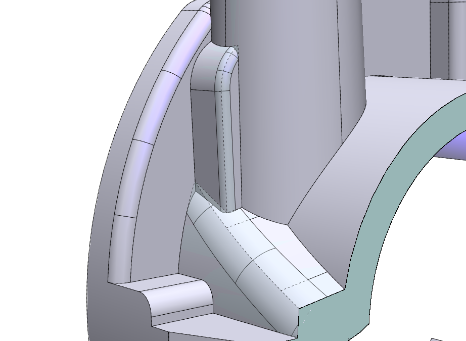
Interactive Modeling relies on the principle of face “extension” that allows the identification of the new intersections between the moved faces and the solid. In the presence of blend surfaces or in general between tangent faces, the extension in the area of tangency of the face does not usually allow the identification of the intersection. The change is thus unfeasible. In these cases, it may be useful to use the “Fillet Recognition”: the faces recognized as a fillet are removed and rebuilt.
Fillet Recognition
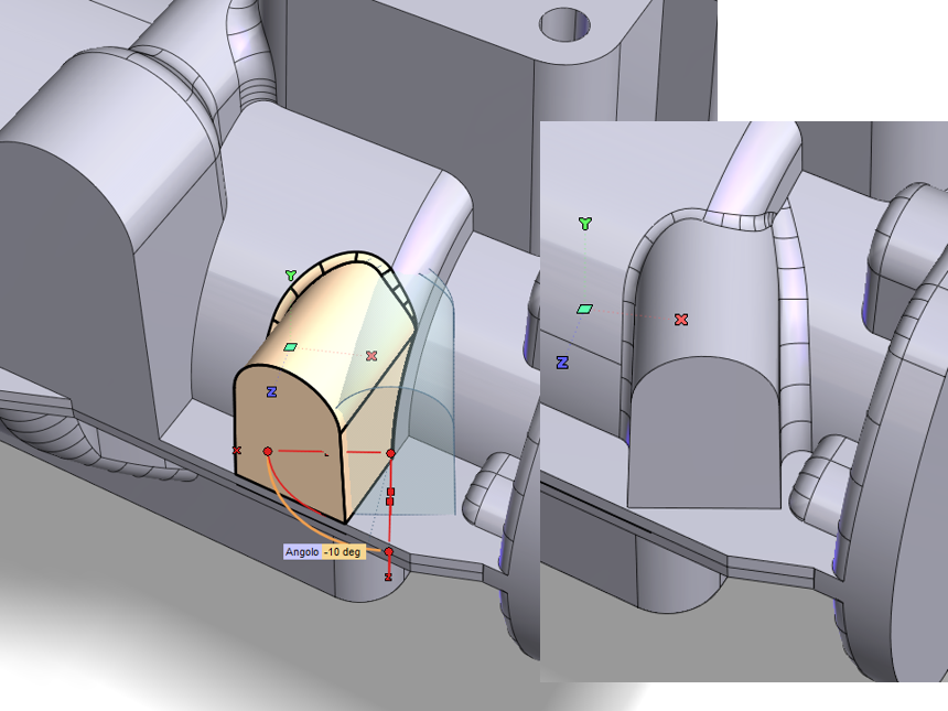
In the most complex cases, it is always useful to simplify the geometry before proceeding with the change. Using the Remove Faces command, first remove the faces of the fillets, obtaining an edge-shaped geometry, then run the Move Faces command. A typical example consists in applying a draft to the filleted faces.

Remove Faces
Another approach consists in fixing small modeling errors, by selecting directly the areas to be removed.
Geometry Simplification
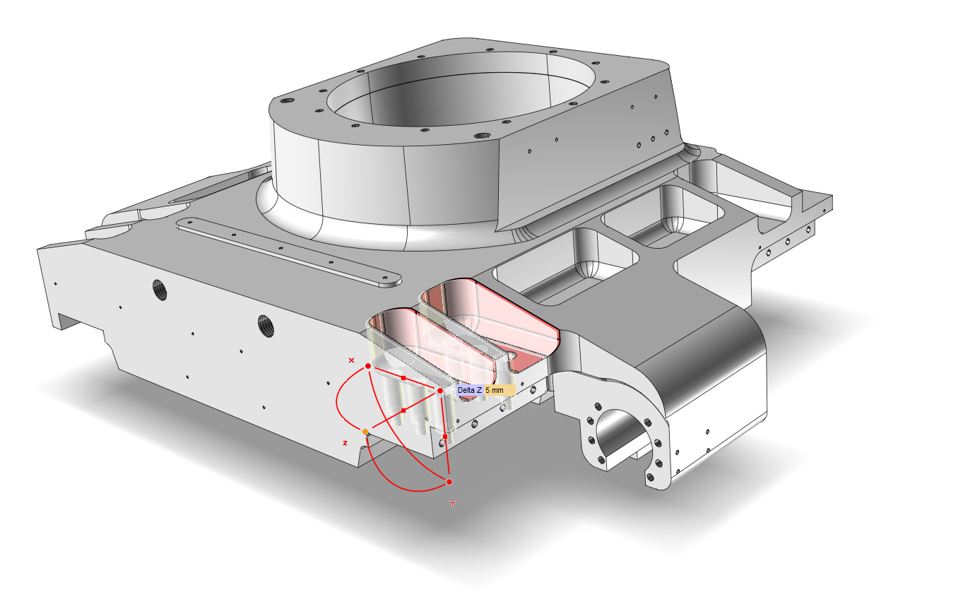
The use of the Remove Faces command, after the selection of “propagated faces” allows you to quickly delete the cavity of a solid and get only the full external volume. This operation is often used in melting details, to remove internal cavities and use the resulting geometry in the mold.
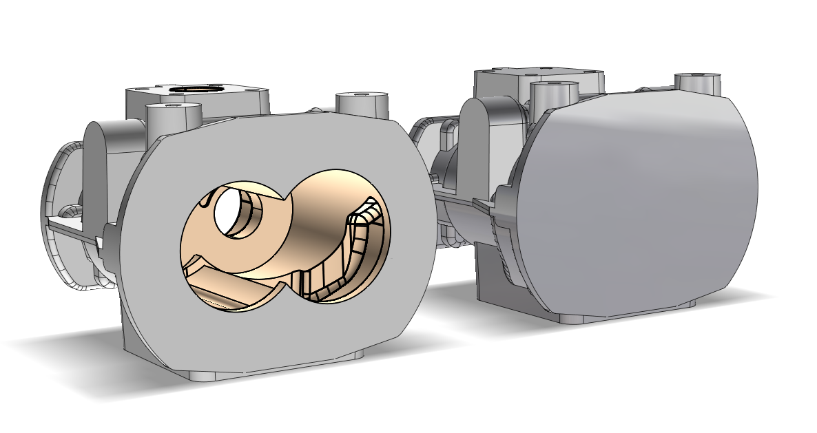
Remove Faces through the selection of “propagated faces”
In the next article, we will see how to apply Interactive Modeling on an imported geometry. We will also analyze the use of the offset function on the faces in order to apply thickness/allowance and to close open solids
See you soon!