
Top 10 Features: Sheet metal
The focus of this article is on the features of the sheet metal design available in ThinkDesign. In particular, we’ll deal with the functions to design bent sheet metal models.
With bent sheet metal we mean the typical features that allow you to get the shape of the detail designed, starting from a flat metal sheet, cut out along the shape to be realized through welding and bending operations. These features have various fields of application according to the design method and/or the approach used. And these, in their turn, are influenced by the characteristics of the material chosen and the shape to be realized.
The approach to produce a detail in bent sheet metal includes a number of typical processes. Here are the most important ones:
- cutting of the shape of the flat metal sheet, executed with cutting machines such as laser cutting, oxygen lance cutting or punching;
- bending in the specific areas of bends, which requires specific machines and processes, as bending and roller leveling, according to the type of bend to be realized;
- execution of special features, such as forming or notching, to create slits, air intakes, punching and holes for fixing screws or rivets, etc.
In ThinkDesign, one of the most important advantages in the use of the sheet metal feature is that designers, by means of a series of functions and parameters, can get all the information necessary for the realization of a particular model, which is soon ready for production. The 2D developed view, for instance, can be used for cutting the metal sheet.
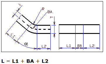
To be more practical, let’s analyze the process to produce a base element. The starting point is a flat rectangular shape, to which we add a bend feature (Flange).
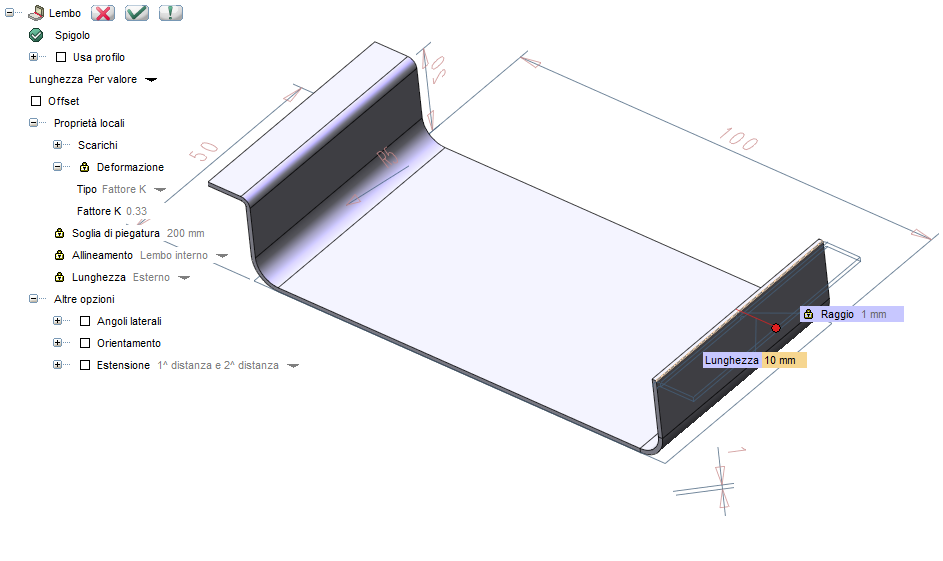
The operator disposes of a specific command with a series of parameters which allow the control of the main features of the bend processing, such as the bend length and radius, the type of deformation and the characteristics of the relief to be carried out.
These parameters refer to the actual size of the model. This information saves time to the designer who, in this way, can avoid calculating in advance all the parameters and the necessary developments. The flat developed view carries out automatically all the necessary calculations to perform a precise cutting of the metal sheet, and also all the features relating to the bending process (bend lines and angle, etc.).
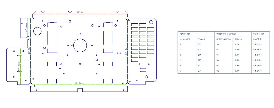
Moreover, the 2D developed view of a sheet metal detail (Flat Pattern View) calculates, for each bend, the relative bend allowance (BA), taking into account the bend radius and angle, and the thickness of the material as well.
The development can be calculated according to different criteria: in some cases the neutral axis (K factor) is kept into account, in others, such as the “Bend Deduction”, depend on the type of material that appears in specific tables (Bend Table Manager). Besides that, a series of properties parameters allow various representations of the bend lines – with hatches and different colors – so that the latter can be directly interpreted by the CAM systems for cutting and nesting. To insert an additional technical detail, consider that the 2D view can be exported to DXF or DWG format.
The functionalities for the production of sheet metal details are directly integrated into the 3D modeling environment; this means that the designer disposes of the parametric solid modeling features that allow a very flexible and simple approach to the realization of the model. By means of the Unbend and Rebend commands it is possible to apply Slot or Drill features to the solid in both developed and bent statuses thus getting the correct development.
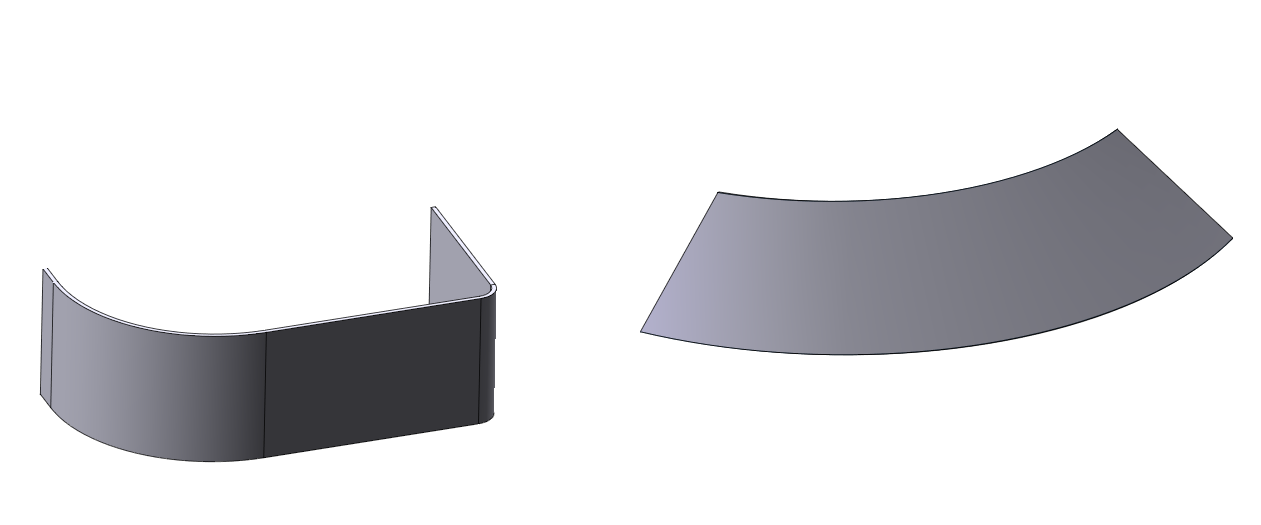
So far we have talked about standard bends, but there are details that require more complex developments. The parameters to be set include a threshold value that allows the definition of the maximum radius for the creation of the bend with the bending machine. Beyond this value, other bending techniques must be considered, such as, for example, the roller leveling. In this case large radii, conical radii and ruled surfaces can be unbent directly along the length of the arc, without taking into account the bending indications (bend lines and the bend allowance calculation).
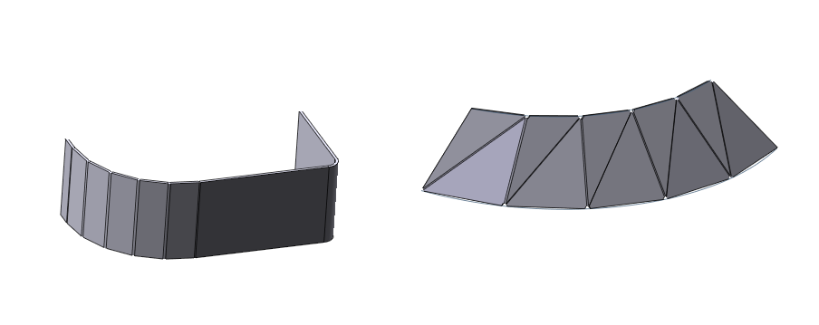
With the “Step Bend” function, it is possible to obtain, by performing a set of regular bends through a sequence of steps, an approximation of the desired shape.
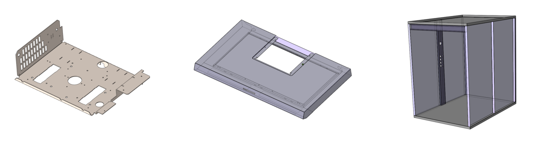
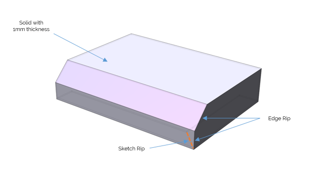
For example, to create a protective casing, first define the overall dimensions and the thickness of the sheet, then empty the solid while creating the shell (using the Solid Shell function) and, finally, carry out, through the “Rip” function, the notches of the needed sides. With this workflow it is extremely easy to produce the initial shape; the operator has to focus exclusively on the main dimensions of the casing, thus making parameterization easier.
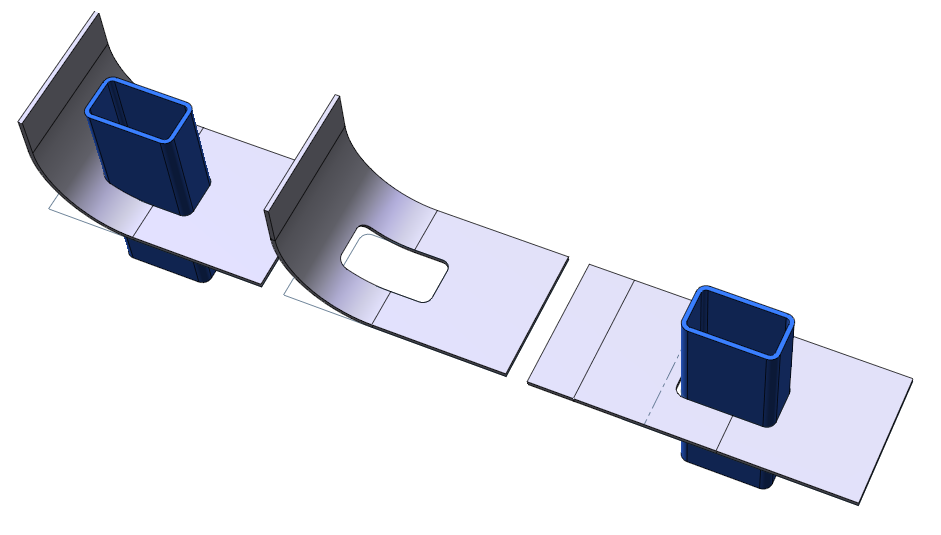
Let’s consider now the represented solid, which has been obtained through the two features of Sweep and Shell obtaining a thickness of 1 mm.
The opening zones have been defined by applying the function of notching with the “Edge Rip” and “Rip by 2 points” functions, then, the relating bend fillets have been automatically carried out with the Unbend and Rebend functions.
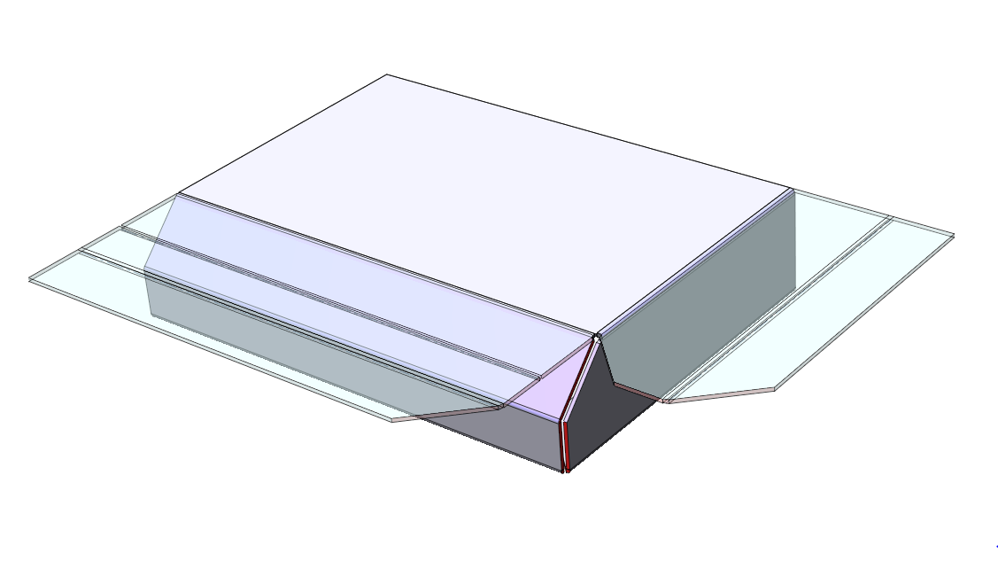
In this way, both the unbend process and the shape creation are simple and immediate, since the flanges have been created by copying the geometries, and the clearances in the notches are minimized, thus making welding easier.
In the next newsletter we will continue to deal with the subject of sheet metal by deepening the following aspects:
- Management of notches;
- Use of specific features with the Smart Objects to handle areas of deep-drawing;
- Possibility to produce the components of a protective casing using the Sheet Metal Wizard;
- Possibility to unbend details imported with STEP files.