
Top 10 Features: Smart Objects – Part 2
Part 1 focused on the definition of Smart Objects. Let’s now try, with an example, to identify their main features.
A Smart Object must:
- Be simple to carry out, so as to be applied with a minimum of initial information and inserted data;
- Be standardized, when required, and therefore contain a set of standard parameters, clearly identifiable and possibly included in pre-defined configurations;
- Contain useful information and descriptions available to all the users of a technical department.
Let’s now consider a practical example. Let’s suppose we want to define a Smart Object to create the housing of a parallel key on a shaft and the solid to represent it.
The features necessary to create the solid and the corresponding housing use profiles for which you need to specify the dimensional parameters and also the work planes which the latter refer to. Therefore, you will need to insert parameters and references of the profile or features, in order to be able to subsequently apply the created Smart Object.
A useful recommendation: the features and the selected profiles should share the greatest quantity of references, so as to minimize the number of parameters and inputs necessary to then apply the created Smart Object.
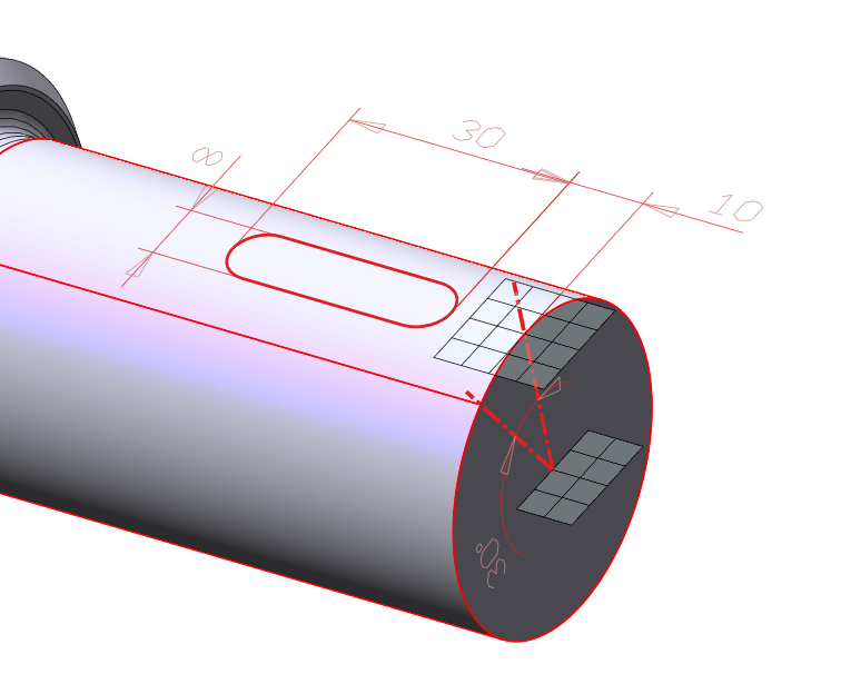
With reference to the example below, to perform the slot that will be used as the key housing, you need to draw a tangent plane to the cylindrical face of the shaft, and then define the shaft diameter to apply the key. In our case, the flat face of the cylinder can be used as the first reference. From it you can derive the center to be used as the anchor point of the Smart Object. The created profile will have two reference lines, coincident in the center, and a dimension to control the angle.
You can build the tangent plane to the cylindrical face using a ‘Datum Plane‘, i.e., in our case, a perpendicular plane to the slanted reference line, passing through the center and parallel at a given distance. The distance from the created parallel plane can be an adaptive measure referring to the cylinder radius (select the cylinder side).
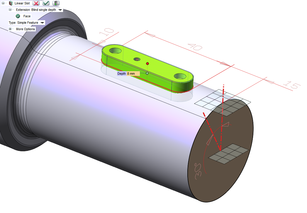
Let’s create the key using the upper profile: the linear sweep will be created with the symmetrical height and the sweep height will represent a further parameter.
You can use the same profile to create the key housing. When creating the slot, if you select the same face that was used as the reference for the initial profile, you could avoid inserting a new reference.
After completing the necessary features, you can start defining the new Smart Object.
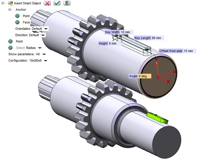
First assign it a name with which it can be saved in the library, then select the features and the profiles to be used. You can carry out this selection directly on the model, by selecting the involved faces, or in the model history tree. The selected feature/profile will be marked with an asterisk.
In the ‘Properties‘ section, choose the ‘Anchor point‘ that will be necessary to position the Smart Object. You can hide any Datum planes or reference profiles used before confirming the creation of the new object, so that they will not be visible when positioning the Smart Object.
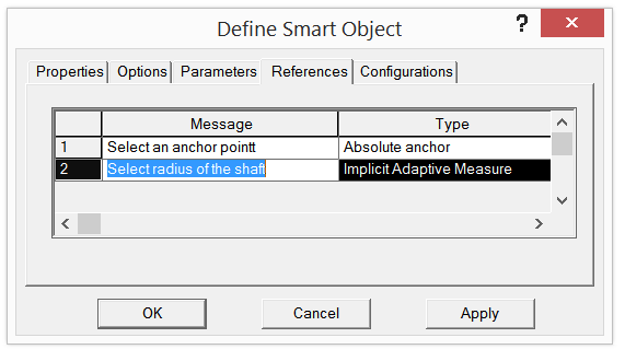
The ‘References‘ section shows the data required for inserting the Smart Object. In our case, having built both the features and the solid on the profile of the two incident lines, the only information still required will be the orientation, the anchor point and the selection of the radius of the tree used from the adaptive measure.
You can save the message that is shown during the creation of the Smart Object, so that more information can be available to other users who can easily reapply the feature.
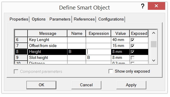
In the ‘Parameters‘ section, instead, you can define the exposed parameters, i.e. the parameters that can be modified. In our case, assigning also the ‘Names‘ you can define some variables and create expressions between the features: for example, you can link the B parameter (key height) with the feature parameter of the slot depth.
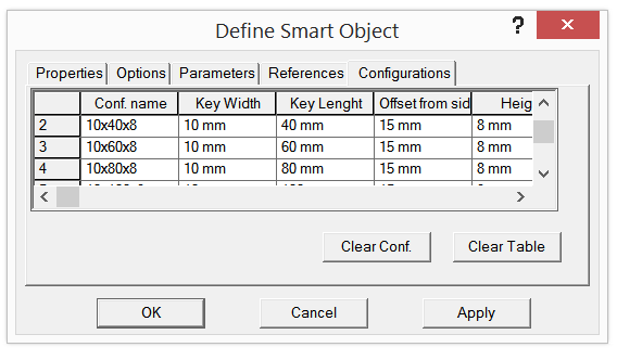
Moreover in the ‘Settings‘ section, you can store a set of standard configurations containing the exposed parameters. This allows you to save some pre-defined configurations according to the internal regulations with regard to the exposed parameters.
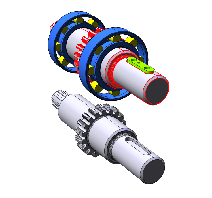
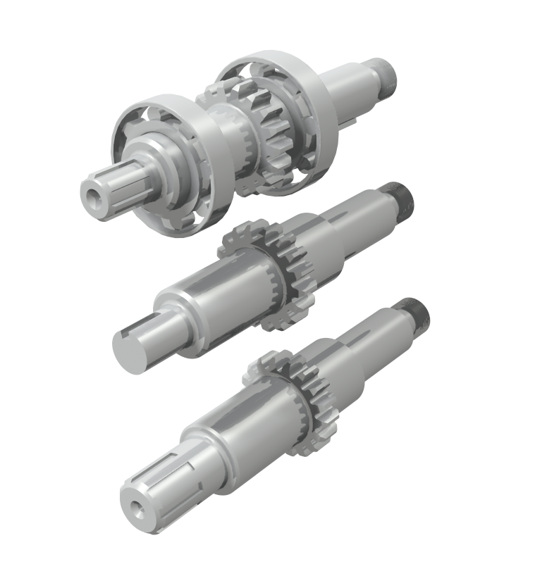
The image below shows an example of implementation of the Smart Object just created.
By using the Smart Objects approach, you can implement a set of design rules that can be applied again in parametric and simplified mode. Smart Objects are a good opportunity to standardize features of common use, by saving a part of the information necessary to implement them in a library that will be shared among all users in the technical department.
Make good use of Smart Objects!