
Top 10 Features: Sheet metal – Part 2
Sheet metal detail design in the integrated modeling environment.
In Part 1 of this article we analyzed some features of ThinkDesign used for the design of bent sheet models. Thanks to a set of functions and parameters, designers can obtain all the necessary information for designing a specific model immediately ready for the production.
Part 2 of this article, focused on the same subject, describes some additional features that are useful for the design of sheet metal details in an integrated modeling environment.
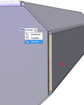
To be practical, let’s consider the sheet metal stresses that can be generated on bending a flange or in the presence of intersecting bend lines, when they are close together; such stresses can cause stretching or breaking. To avoid these problems and facilitate the bending operation, cuts or undercuts are performed in the sheet metal. A typical example is represented by the partial bend on a side, with the bend line internal to the thickness:
The sheet metal functions of ThinkDesign can perform automatically and under certain conditions, different types of rips by using the correct parameters according to the feature to be executed on the flange. The immediate advantage of this is the possibility to choose the most suitable type and size of relief to be performed. The reliefs, with a rectangular or oblong shape, are available among the parameters of the drop-down list of “Bend Relief”.
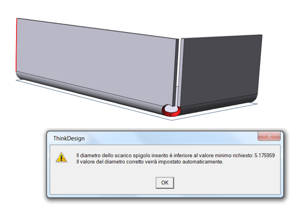
In the case of bends which intersect by generating an edge, the option to control the relief is particularly appreciated. Through the parameter “Flange Corner”, this option verifies the behavior and the type of the relief generated in the construction of the flange. During the definition of the relief size, generated on the basis of the bend radius and the necessary flattening operation, ThinkDesign provides the designer with the minimum relief value to be used, thus proving to be a very helpful tool.
The same result can also be achieved by starting the modeling from an existing solid. In this case the user must first define the external dimensions of the various flanges, and, subsequently, by using the notching commands, he/she can identify the areas where the openings must be performed to get the final unbending.
Here is an example:
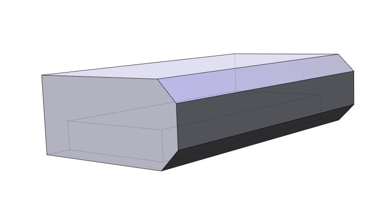
By using the “Solid Shell” command, apply a constant thickness (that of the sheet metal) to the solid represented here above, and remove the non-useful faces.
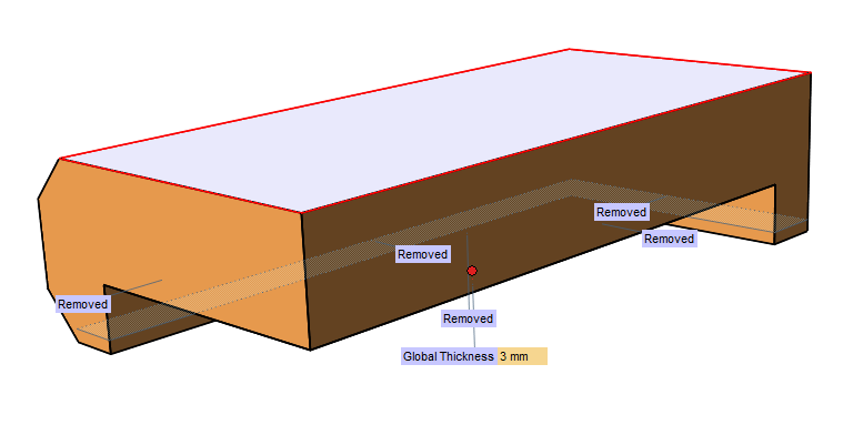
Then, by using the Sketched Rip command, select 2 points and set the minimum opening required (e.g. 0.1mm). Also any eventual reliefs on the vertices will be automatically generated.

The “Unbend” and “Rebend” commands add the bend radii according to the default parameters set for the sheet metal, and the “Close Corner” function allows you to extend the flange by adding the material needed to further minimize the relief area. In the example shown a “Close Corner” feature has been applied with the “Middle” option, to position the edge end point at mid-thickness and leave room to insert welding.
ThinkDesign further simplifies the geometry to be exported to CAM applications for cutting: activate the “Remove relief” option in the flat pattern view. This option is necessary to insert bends in the model.
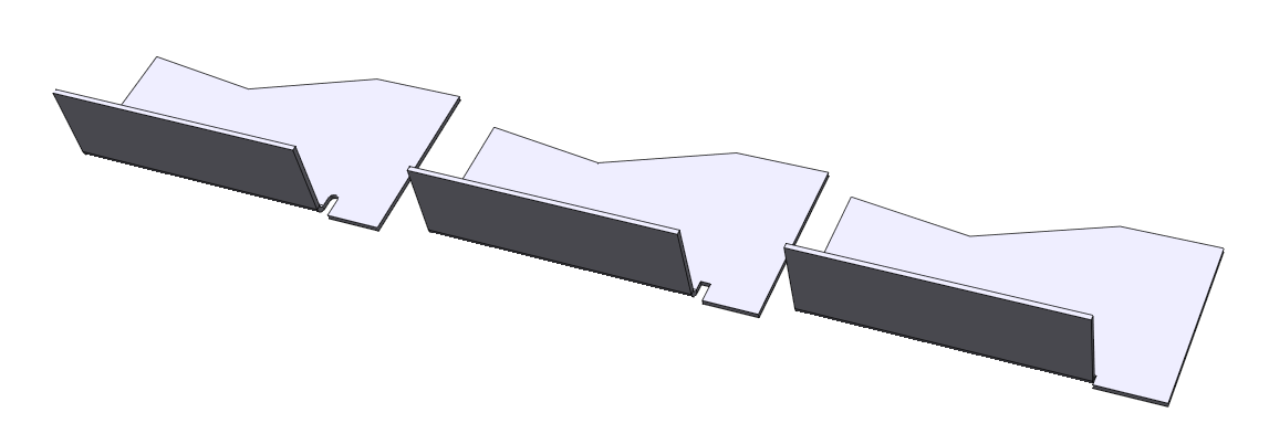
When building a protective sheet metal to cover all sides of an object, more parts are often required because a single sheet metal element would be insufficient. First create the various parts separately and then assembly them.

The “Sheet metal Wizard”, allows you to easily define the rules to set the necessary features – such as bends or notches – on a full solid detail. ThinkDesign generates the necessary parts according to the cuts and applies the proper sheet metal thickness and the necessary bending features.
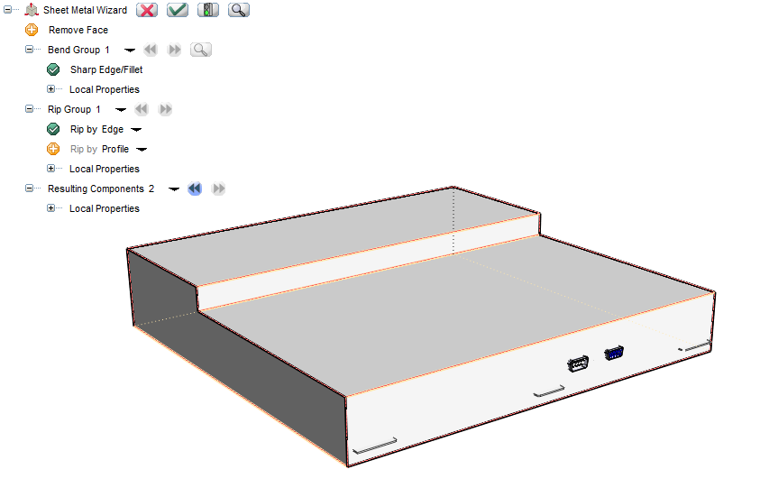
This type of approach is particularly useful in the presence of many details because it simplifies the parameterization and skips the step of assembling the details.
The single details can be further modified by applying additional features to the part.
ThinkDesign provides a library of smart objects for the typical sheet metal machining processes. Thanks to this rich archive it is possible to apply punching or recurring machining processes for clips, chocks, slots, vents, punches for screws, etc.
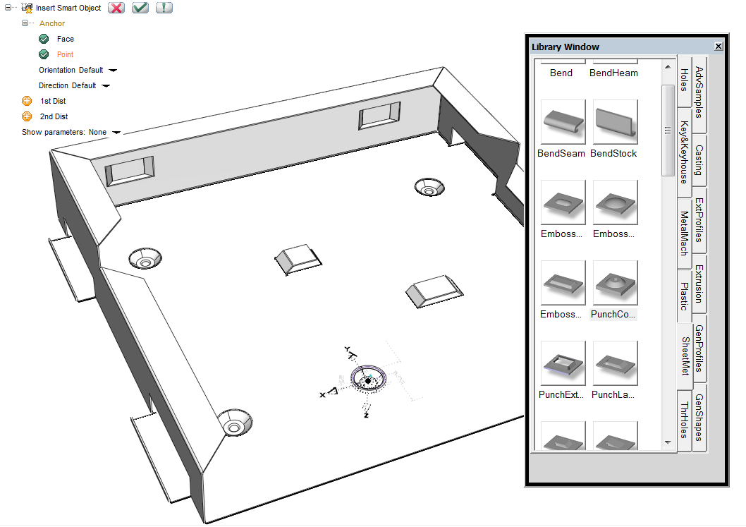
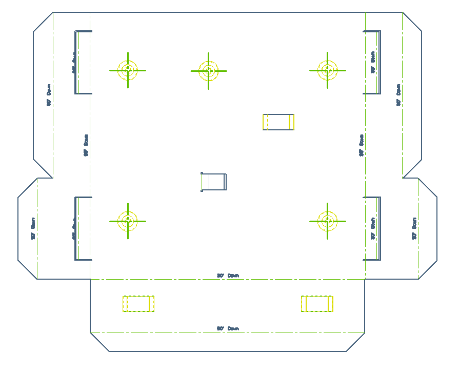
In a flat pattern view, you can easily recognize the different features: a drawing can be recognized for the presence of areas with closed tangent faces on a plane and in case of Smart Objects with bends, the bends are flattened. The image below shows an example of flat pattern view of the object created.
By using the Smart Objects, it is possible to download, reuse and share in full or in part, the modeling sequences in order to carry out new features.
We will develop this topic in depth in a future article, but it is interesting to explain in this context that the designer has the possibility to inherit the thickness property, so that the feature can be adapted to the thickness of the sheet metal detail on which it is applied. This is made possible by assigning the variable _SM_THICKNESS to the expressions of the Smart object under development.
Another valuable functionality is represented by the possibility of applying the “Unbend” and “Rebend” features to details imported directly with STEP files. The static geometry imported, can be flattened by applying the typical rules of a sheet metal bent part. The general controls to execute on the imported files are the following:
- The geometry must have a constant thickness.
- The minimum reliefs and openings must be represented.
In conclusion, ThinkDesign offers an intuitive, feature-rich environment for unbending and designing details in bent sheet metal: a specific 3D modeling environment is not required, but, the integration with the solid modeling functions provides the user with the maximum potential to work as effectively and quickly as possible.