
Focus On: Colors and Materials in ThinkDesign
The availability of colors and materials, together with a good strategy in the use of the features, can greatly facilitate and speed up design, besides improving the technical documentation, by making it easily accessible and more pleasant to read.
ThinkDesign provides you with powerful features and tools that allow you to assign different colors and materials to different graphical entities. The color attribute was initially used only to distinguish the entities, or assign the thickness to a 2D- drawing print. Now the distinction by colors can be effectively used for a better communication and a good standardization throughout the company. It also helps you to facilitate the processes of importing and exporting models and drawings to other systems that interact with design. As a consequence, a good planning in the management of colors and materials allows you to unify and standardize the models and drawings of your project archive.
Have you ever wondered:
- Can I create a library of colors and materials?
- To which entities can I assign colors and materials?
- How can I assign a specific weight/material to solids and calculate the weight of an assembly?
- How can my library become a standard for the whole technical department?
- What benefits can I get from an efficient use of colors in the design of 3D models and assemblies?
- What happens when I export my model?
- About the model/drawing documents of my technical archive, do they all comply with the same convention for the use of colors and materials?
If you happen to linger on at least one of these questions and you have been caught by some doubts, you may want to deepen the topic, by searching for all the functions that ThinkDesign makes available.
With color and material, we mean two distinct ‘Properties’ that can be assigned to the graphical entities. With graphical entities, we intend dimensions, texts, lines and curves, surfaces and solids but also solid faces, components, and assemblies.
In particular, the ‘Color Property’ can be assigned to the entities through a ‘Color Map’ that is used and saved in the current document.
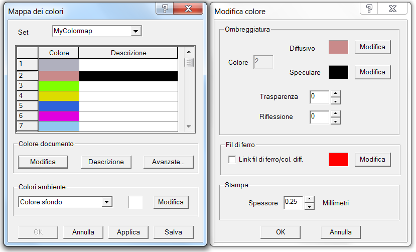
The colors available are the numbered from 1 to 64, and for each of them, you can define a set of parameters: specular color, wireframe representation color, print thickness, transparency, reflection, etc. You can define a ‘color map’ and save it in the template file’: from this moment on, any new document created, will refer to the saved parameters. The ‘Color Map’ provides also some of the colors of the user interface, to be used in particular situations, for example, as an alternative background color to be used when editing a profile. Moreover, some colors are ‘reserved’ and used only for the previews (numbers 28-32). A tip: if you want to change the display color of the selection window, you only need to change color 31, corresponding to the wireframe parameter.
During the design of an assembly, it can be useful to assign the color property to both solids and components. Thanks to the parameter ‘Show closed components with component color’ you can choose the type of representation to use, giving priority to the display of the solids rather than the components. This allows you to switch between the two views, highlighting, for example, the assembly details with respect to the functional groups.
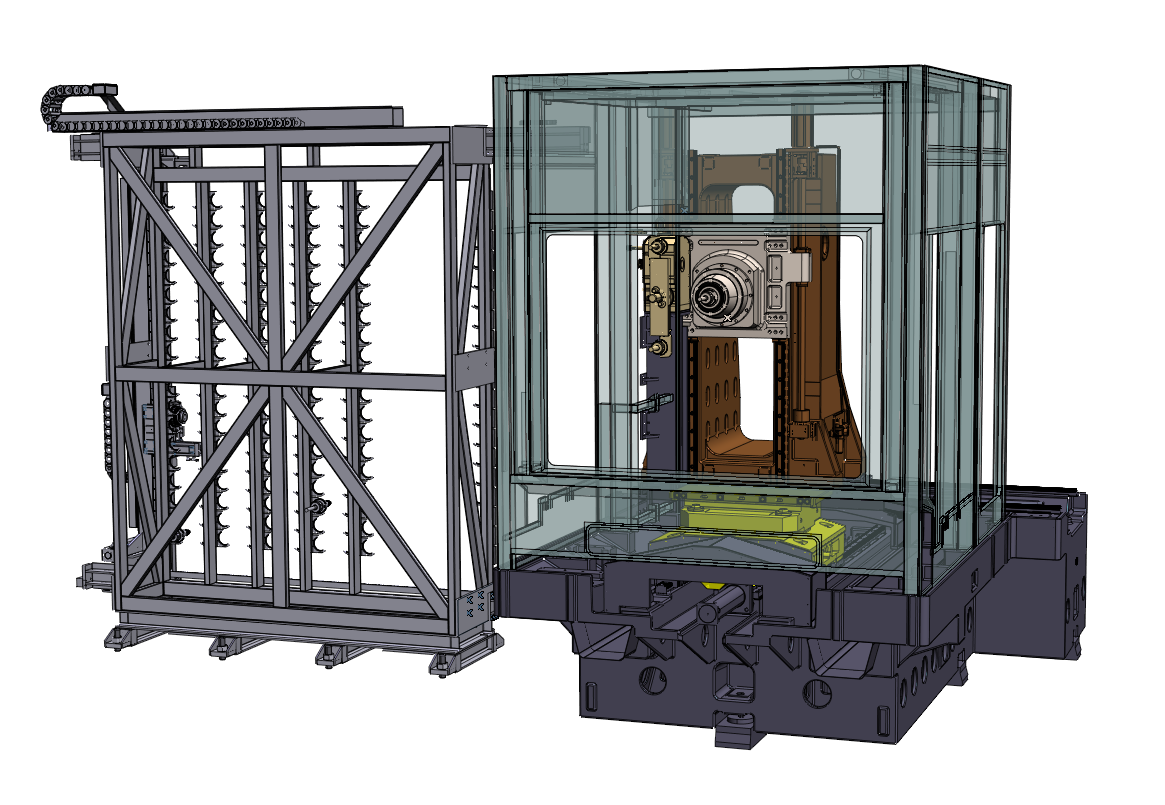
View by color of components
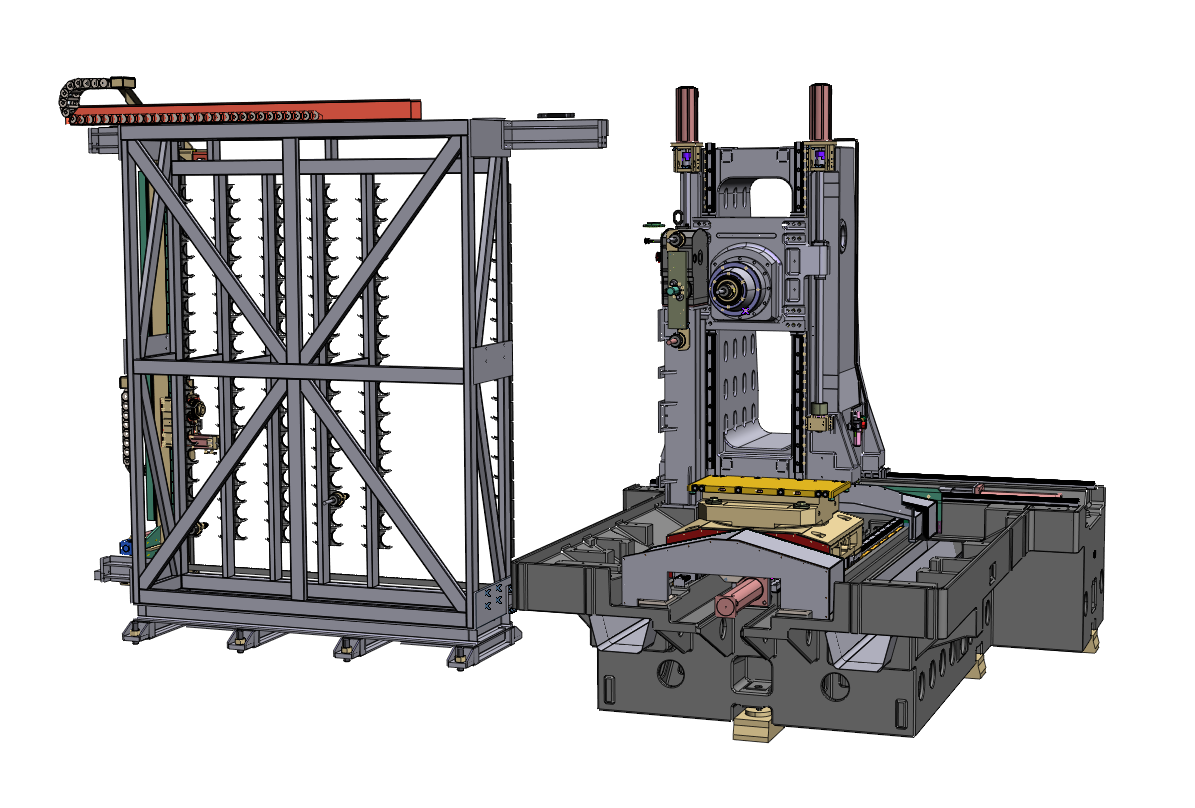
View by color of entities
Transparency offers a further possibility. By assigning a color with transparency to a component, you can view in transparency all the solids/surfaces contained in the assembly. Moreover, the colors assigned to both entities and components, can be used in the drawing representation, by creating views that inherit the drawing properties (see the View parameters in ‘Drawing -> View Attributes’).
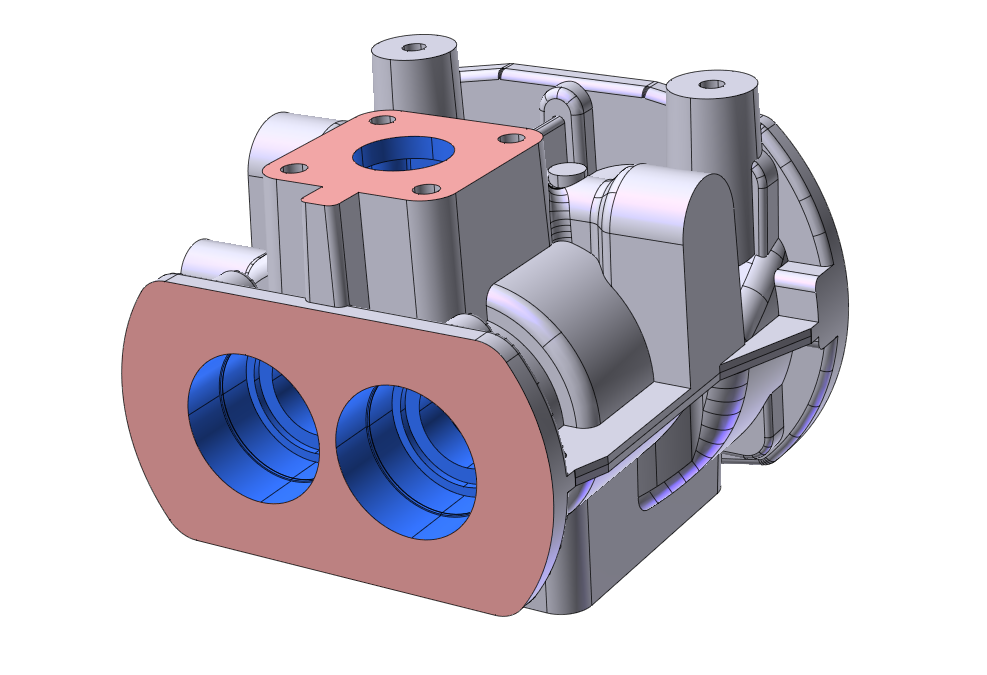
A further possibility is available for the solids/skins, since it is possible to assign to one or more faces colors other than the one assigned to the solid, in order to highlight particular features.

When exporting the solid, the colors assigned to the faces are maintained thanks to the use of the STEP AP214 standard. A CAM system or a provider who receive the STEP file can, consequently, recognize and distinguish specific faces of the solid and apply features or specific finishing.
Stay tuned, and in the next article, you will find a further insight into the management of the material properties, the definition of the Rendering density and appearance functions and the library organization.